How to Configure Dual ISP Network with GlobalProtect VPN using a Virtual Router and Policy-Based Forwarding
Symptom
This document explains how to configure a Palo Alto Networks firewall that has a dual ISP connection in combination with GlobalProtect VPN. One ISP link is used for non VPN traffic and the other is used exclusively for GlobalProtect VPN traffic.
Configuration Goals:
- Dual ISP connection in combination with VPN tunnels.
- Simple Global Protect VPN Gateway/Portal and Client
- 1 ISP is preferred for LAN to Internet traffic - Default route towards ISP1
- Other ISP link used for GP VPN traffic
Environment
- Pan-OS
- Global Protect
Resolution
ISP1 is used as the primary ISP. ISP2 is the GlobalProtect VPN traffic ISP.
Interface Configuration
Configure four interfaces:
- Ethernet 1/1 - 10.193.19.1/23 - LAN Zone Interface
- Ethernet 1/2 - 192.168.2.11/24 - Zone ISP 1 Interface
- Ethernet 1/3 - 10.193.17.1/23 - Zone ISP 2 Interface
- tunnel.1 - 172.16.1.1/24 - Zone VPN Interface
The VPN Zone
GlobalProtect VPN will be configured soon. A requirement for the VPN to function is a tunnel Layer 3 interface. This interface is a virtual interface that has all the features of a physical interface. As such it can be configured in a zone of its own.
In this configuration the tunnel.1 interface is placed in the Zone VPN. Whenever VPN traffic is initiated by the customer, this traffic will be seen by the firewall as egress from the tunnel.1 interface and VPN Zone. The VPN traffic needs to reach the ISP2 Zone .
Network Security Configuration
Configure basic networking and Security Policies to allow traffic between:
- LAN and ISP1
- VPN and ISP2
Add Default Route 0.0.0.0/0 to ISP1:
Allow traffic to the 2 ISPs by using NAT Rules
In order for the outgoing traffic to be translated from internal IP addresses to outside IP addresses, we need to use some kind of Source NAT. In this example Dynamic IP and Port NAT is being used. The global IP will be the outgoing interface IP.
NAT to ISP1:
- Source zone : any
- Destination zone: ISP1
- NAT Type: Source NAT
- Source translation : dynamic IP and Port ; Interface : Ethernet 1/2 ; IP address: 192.168.2.11
NAT to ISP2:
- Source zone : any
- Destination zone: ISP2
- NAT Type: Source NAT
- Source translation : dynamic IP and Port ; Interface : Ethernet 1/3 ; IP address: 10.193.17.1
At this point, traffic should be able to reach ISP1 from LAN and ISP2 from GlobalProtect VPN that has yet to be configured.
ISP1 Connection Test

Policy-Based Forwarding
Since we are passing the default route 0.0.0.0/0 to the GlobalProtect client, the default behavior of the firewall is to route the packets towards ISP1, because of the default route set up in the static routes of the Virtual Router .
The PBF will modify routing behavior in the following way:
All packets initiated from interface tunnel.1 that are heading for any other address other than directly connected LAN subnetwork or the directly connected ISP1 subnetwork should be forwarded to interface ethernet 1/3 , going to ISP2. The next hop is the IP pointing to the ISP2 router that goes to the Internet. There is no need for Symetric Return since the NAT will identify NATed sessions and translate it back to the initial internal IP. This will overwrite all packets going to an unknown address originating from the GlobalProtect tunnel interface.
GlobalProtect Configuration
This implementation of GlobalProtect is a basic one, without any special features.
For a more detailed GlobalProtect configuration, check other Knowledge Base articles, Configuration Guides or the official Administration Guide in addition to the following references:
How to Configure GlobalProtect
How to Generate a New Self-Signed Certificate
GlobalProtect Configuration Tech Note
GlobalProtect Setup
Gateway IP: 10.193.19.1
GlobalProtect Client IP Pool: 172.16.1.2 -> 172.16.1.55
Tunnel Interface: tunnel.1
Tunnel Interface IP: 172.16.1.1
Routes passed to clients : 0.0.0.0/0 - The clients will have as default gateway 172.16.1.1 - tunnel.1 interface
Detailed configuration:
Certificates
GlobalProtect Gateway
GlobalProtect Portal
Once this is set up, the GlobalProtect Client should be able to connect to the GlobalProtect Gateway:
Client Connection to GlobalProtect
Connection is successful. Assigned IP address is 172.16.1.2:
A Virtual interface is created on the Windows machine:

And, the default route is being injected:
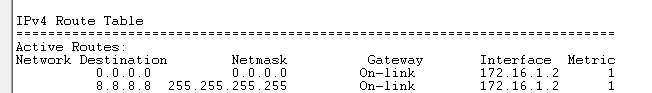
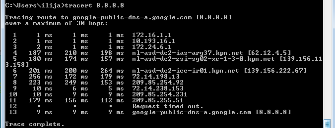
Connection to Internet through ISP2 is working:
Additional Information
Note: This configuration does not achieve a failover if any one of the ISPs is not reachable.
owner: bbolovan