HSRP:- Ideas / suggestions thoughts on how to achieve this using Palo Altos in Active/Passive.

cancel
Showing results for 
Show  only  | Search instead for 
Did you mean: 
Announcements
Please sign in to see details of an important advisory in our Customer Advisories area.

HSRP:- Ideas / suggestions thoughts on how to achieve this using Palo Altos in Active/Passive.

L4 Transporter

Greetings Evereyone,


I need some ideas / suggestions / thoughts on:


For reference, I just attached a hand drawn network diagram.


Just to provide a brief description, I have a network scenario that presently uses HSRP to maintain Active/Passive configuration on the border Cisco FWSMs firewalls.  I will be replacing these FWSMs with Palo Altos in HA.

The ‘Inside’ subnet uses the subnet address 1.2.1.0/24 (on vlan 118) and there are layer 3 interfaces on A and B and the two Cisco FWSM’s (which are hosted by A and B), although only B and A participate in HSRP to provide the active interface.


As the only link between B and A (1/3 on each) carries the vlans used for the wireless network and none of the firewall vlans, then the HSRP communication for the ‘Inside’ subnet is being achieved through the Cisco FWSM’s.  Referring back to the diagram, there is a link between D and C (which host the FWSM’s) that carries all the firewall vlans including vlan 118 on the inside subnet.  


This means that should there be a loss of either B or A, the remaining device will take the active address (1.2.1.1) and traffic from inside will continue to be forwarded to the gateway of last resort on the active FWSM (1.2.1.4)


Similarly, from the diagram, HSRP is used on the ‘Outside’ subnet (3.2.4.0/24) with the active interface shared between the two border routers.  There is no link between the two border routers.  Hence any HSRP communication between these two routers passes through the FWSMs in D anc C. 


My concern is, can this be achieved in Active/Passive configuration on the Palo Altos?  Will the PA’s be able to maintain these ‘floating’ addresses if we move from HSRP to VRRP?


Any thoughts, suggestions, ideas on how I can achieve the same level of resilience using a shared address with the Palo Altos would be appreciated.


Many Thanks

Kind Regards,

Kalyan

5 REPLIES 5

L6 Presenter

Im trying to sort it out, so please verify that I have understood your case correctly 🙂

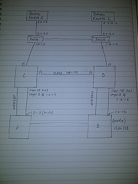
Border Router 1: 3.2.4.2/29

Border Router 2: 3.2.4.3/29

Border Router Floting: 3.2.4.1/29

FWSM(1?) outside: 3.2.4.4/29

FWSM(2?) outside: 3.2.4.5/29

FWSM outside floating: 3.2.4.6/29

FWSM(1?) inside: 1.2.1.4/29

FWSM(2?) inside: 1.2.1.5/29

FWSM inside floating: 1.2.1.6/29

Switch C: no ip

Switch 😧 no ip

Router A: 1.2.1.3/29

Router B: 1.2.1.2/29

Router floating: 1.2.1.1/29

This way the logical L3 flow is:

Border Router 1/2 <-> FWSM <-> A/B Router

If the above is correct then when replacing FWSM with a PA in Active/Passive the current "floting ip" in your HSRP setup of FWSM is what you will set as ip on your PA devices.

That is because PA doesnt use HSRP/VRRP - it uses only one ip which is "physically" moved to the current active device (you can compare it to cold standby, if PA_A fails then PA_B "boots up" and take ownership of all ip's (except mgmt int) previously used by PA_A).

So this solves the FWSM <-> A/B Router traffic.

Now for Border Router 1/2 <-> FWSM it gets more tricky.

At first I thought you could solve it with setting up L2-interfaces (so you have L2 connectivity Border Router 1 -> PA_A -> PA_B -> Border Router 2) but then im not sure how PA handles L2 interfaces when in passive mode.

Will the L2 interface be shutdown just like L3 interfaces are on passive devices?

Before I confirm the above details, I would like to ask one question:

"If the above is correct then when replacing FWSM with a PA in Active/Passive the current "floating ip" in your HSRP setup of FWSM is what you will set as ip on your PA devices.."

--> Are you talking about IP: 1.2.1.1/29?  If yes, where will have to set this up?

Many Thanks for looking into it.  I shall come back with more information on this.

For example (replacing current FWSM with PA):

FWSM(1?) outside: 3.2.4.4/29

FWSM(2?) outside: 3.2.4.5/29

FWSM outside floating: 3.2.4.6/29

In this case you will use 3.2.4.6/29 on the outside interface of your PA.

While:

FWSM(1?) inside: 1.2.1.4/29

FWSM(2?) inside: 1.2.1.5/29

FWSM inside floating: 1.2.1.6/29

means you will use 1.2.1.6/29 on the inside interface of your PA.

The above gives that you wont need to alter any routes (nexthop ip's).

However if you like you could shrink the networks down to /30 but not if at least one of the sides uses HSRP (because HSRP needs two physical ip's and one floating (which will be used by the current active HSRP device)).

To give more information on this;

FWSM1 is 1.2.1.4

FWSM2 is 1.2.1.5

The Cisco FWSM's, obviously in Active/Passive configuration, each firewall shares the active address for the appropriate interface.  This does not use HSRP to share this address but as per the present configuration on the Ciscos, the stateful failover mechanism in both firewalls share the same active address, the .4 address.

For example considering outgoing traffic:

A packet reached the core routers ( for example B) and wants to out to the internet; the packet is directed to gateway of last resort (1.2.1.4), which is the floating active address which resides on the inside interface on the firewall(s) (as you have determined).

Upon reaching the firewall the packet is then routed to 3.2.4.1, which is the HSRP address which is shared by the Border Routers and held by which ever Border Router is the active device. 

The important thing to note here is that without HSRP running on the 2 border routers, the firewall will not have an active route to send its outbound traffic i.e 3.2.4.1

Now considering incoming traffic:

Packet reaches the border routers on the outside interface on the firewall via a static route i.e. 3.2.4.4.  The firewall will then route the traffic (via a static) to the HSRP address through its inside interface i.e. 1.2.1.1.  This IP address is the shared HSRP address between B and A.

The important thing to note is without the HSRP addres on B/A, there is nowhere for the traffic to be sent.

Hence, the key elements to this issue are that, HSRP flows across the two Cisco FWSMs.  For the inside interface it is 1.2.1.1 and for the outside interface it is 3.2.4.1.  This allows for a single static route to be configured on each device and thereby allows to flow in and out. 

Now, is there any way I can achieve this without assigning 3.2.4.6 on the outside interface and 1.2.1.6 on the inside interface and leave the IP address as they are?

Many Thanks

I am pretty much sure that the L2 interfaces will  be shut down and act the same as in Layer 3.  I have not experienced it..neither did I configure such scenarios..

  • 3724 Views
  • 5 replies
  • 0 Likes
Like what you see?

Show your appreciation!

Click Like if a post is helpful to you or if you just want to show your support.

Click Accept as Solution to acknowledge that the answer to your question has been provided.

The button appears next to the replies on topics you’ve started. The member who gave the solution and all future visitors to this topic will appreciate it!

These simple actions take just seconds of your time, but go a long way in showing appreciation for community members and the LIVEcommunity as a whole!

The LIVEcommunity thanks you for your participation!