- Access exclusive content
- Connect with peers
- Share your expertise
- Find support resources
Click Preferences to customize your cookie settings.
Unlock your full community experience!
AWS: GWLB endpoint mapping in Central Design Model
- LIVEcommunity
- Discussions
- Network Security
- VM-Series in the Public Cloud
- AWS: GWLB endpoint mapping in Central Design Model
- Subscribe to RSS Feed
- Mark Topic as New
- Mark Topic as Read
- Float this Topic for Current User
- Printer Friendly Page
AWS: GWLB endpoint mapping in Central Design Model
- Mark as New
- Subscribe to RSS Feed
- Permalink
01-25-2024 01:40 AM
I'm trying to understand the use of GWLB endpoint mapping in an AWS Central Design Model deployment, other than separating VPC traffic flows from that of the GWLB itself - or separating outbound from east-west.
In this model, the source zone on the firewall is determined by the destination address in the encapsulated packet, via the route table associated with the TGW attachment subnet pointing to the GWLBe in the inspection VPC. While overlay routing permits the use of inter-zone policies, all east/west flows are intra-zone and should mandate an override of the default intra-zone rule to deny and log yet I have only once seen this in the reference architecture and observed implementations with explicit intra-zone deny rules.
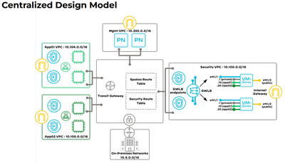
For pre-cloud engineers, these principles are counterintuitive, and the source of confusion observed in community posts concerning mapping VPCs to zones and the use of inter-zone policies, especially when looking at diagrams like this:
(src: P48, Securing Applications in AWS, Feb 2003)
and this:
In these diagrams, we see sub-interfaces depicted on the VM-series instances associated with application VPCs that also match the colour of the VPC. I find this misleading because the source zone on the firewall can only be determined by the destination address in the packet explained above.
The above schema is accurate for an isolated design model where each VPC has a GWLBe in each AZ, and those GWLBe's can be associated with sub-interfaces in PAN-OS and therefore zones. However isolated designs are specifically intended for isolated VPCs and does not support east/west flows between VPCs:
Because GWLB endpoints for outbound and east/west traffic in a Centralised (Centralized) model exist in the security VPC, and a GWLBe is determined by the route table associated with the TGW attachment subnet, sub-interfaces and therefore zones can only be determined by the destination IP. There is (for now) no way to associate a VPC with a security zone in this model, nor do the traditional from/to zone principles apply.
From a traffic engineering perspective, I find it easiest to think of this model as a firewall on a stick (perhaps with an external interface) and the TGW as a policy router (or a backbone connecting routers connected to each attachment). Since all outbound traffic from a spoke VPC (protected network) reaches the firewall over the same link, it all hits the same interface and therefore same zone. When reaching the firewall, all east/west traffic is returned on the same interface (i.e hairpinned, intra-zone) and should be denied by default, and with overlay routing all outbound traffic may still be from the same zone (unless you want the TGW attachment subnet route table to split outbound traffic to a dedicated GWLBe).
I hope this piece of rubber duck debugging helps others questioning life reality and their place in the universe, and that the diagrams are updated to minimise confusion 🙂
Matt
- 2080 Views
- 0 replies
- 0 Likes
Show your appreciation!
Click Accept as Solution to acknowledge that the answer to your question has been provided.
The button appears next to the replies on topics you’ve started. The member who gave the solution and all future visitors to this topic will appreciate it!
These simple actions take just seconds of your time, but go a long way in showing appreciation for community members and the LIVEcommunity as a whole!
The LIVEcommunity thanks you for your participation!


