- Access exclusive content
- Connect with peers
- Share your expertise
- Find support resources
Click Preferences to customize your cookie settings.
Unlock your full community experience!
- LIVEcommunity
- Articles
- General Articles
- Who rated this article
Who rated this article
- Mark as New
- Subscribe to RSS Feed
- Permalink
on 05-13-2020 01:06 PM - edited on 05-30-2023 01:25 AM by kiwi

Palo Alto Networks covers the deployment of the VM-Series Next-Generation Firewall on the ESXi hypervisor in Layer2 mode. Learn about topology, system requirements, and VM-Series Layer 2 Configuration.
Deploying the VM-Series on ESXi in Layer 2 Mode
All virtual machines on the ESXi hosts will be segregated from each other on the network by the VM-Series NGFW by manipulating VLAN tags and preserving existing Layer 3 gateways. The basis for this design is to provide maximum flexibility with regards to VM-Series placement, guest VM protection, and the inherent networking capabilities of the ESXi hypervisor.
This technote will cover a multiple ESXi host environment showcasing east/west traffic separation to demonstrate the Layer 2 capabilities of the VM-Series next-generation firewall.
Topology
A highly available Active/Passive pair of VM-Series next-generation firewalls are positioned between the physical datacenter network and Guest VM workloads. A single Distributed vSwitch will be used in this example topology. Port Groups are used to segregate traffic between the untrusted side and the trusted side of the firewall. To prevent layer2 loops in the virtual and physical networks, each port group will require a different VLAN-ID. The uplink will be configured to trunk VLANs to the physical datacenter switch.

Requirements
This design was tested with ESXi version 6.7u3, vCenter version 6.7, VM-Series PanOS version 9.1.2.
Creating the Network Topology
Often we make virtual networking more complicated than it needs to be. ESXi virtual switches work on similar principles to physical network switches (without MAC Learning). So the first thing I want you to do is to think about the solution as networking—not physical networking, not virtual networking, just networking. Don’t overcomplicate it. The same principles that you would use to deploy our firewall in a physical networking environment are the same methodology you would use to deploy the VM-Series in a virtualized environment.
Building the ESXi network topology is a crucial part of any layer 2 design. The distributed vSwitches by themselves do not necessarily segregate traffic between port groups. The default configuration of a vSwitch, the initial port group configuration, and the vSwitch uplinks create a flat layer2 network.
There is a misconception about what port groups are. Port Groups are simply a collection of virtual ports that share a common configuration set. A port group is not a VLAN. There are many attributes that can be configured under a port group and the VLAN ID is one of those attributes. Port group A and port group B can be in the same VLAN and the guests in each port group will be able to talk to each other. Port groups can be assigned to different VLANs allowing for network to be segmented by VLAN ID.
- Port groups that share a common VLAN ID can communicate with each other.
- Port groups configured with different VLAN IDs are segregated from one another.
- Port groups can also be configured to be access ports (untagged) or trunk ports (tagged).
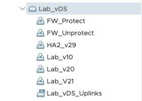
To prevent the possibility of creating Layer 2 network loops, ports groups used for this solution have been configured with different VLAN-IDs. This design calls for several port groups to be configured on the vSwitch.
 Uplink ports LAB_vDS Uplinks Uplink ports LAB_vDS Uplinks |
|
Looking at the Port Group configurations individually, we can see how they are set up. The port groups for the guests are set up as access port groups that have been assigned to a VLAN, but the VLAN is untagged to the guests. The VM-Series port groups are created as trunk ports (tagged) and for simplicity, we have grouped the untrusted VLAN in a single port group and the protected VLANs in another port group for the firewalls.
For the VM-Series port groups ONLY, you have to allow for Promiscuous Mode, allowing MAC address changes, and allowing Forged Transmits. Guest port groups do not need changes to the port group security settings.
The following image shows the three guest port groups: Lab_v10, Lab_v20 & Lab_v21

The following image shows the port groups assigned to the VM-Series. These are the only port groups that need to have their security settings adjusted.

The VM-Series next-generation firewall is configured as a layer two bridge and does not support Spanning Tree. You must ensure that your virtual switching and physical switching is loop-free since there will not be any mechanism to prevent switching loops. You need to ensure your layer2 network is properly designed.
Assign Port Groups to Virtual Machines
VM-Series Firewalls are assigned to the firewall port groups. Network Adapter 1 is used for the firewall’s management interface. Network Adapter 2 is used for the untrusted side of the firewall. Network Adapter 3 is used for the trusted side of the firewall.

The guest machines are assigned to their respective port-groups.


VM-Series Layer 2 Configuration
This section covers the VM-Series next-generation firewall network configuration. All configuration is completed in the PAN-OS web interface.
Zones
A single zone was used in this example. While a multi-zone setup can be used with a layer 2 design, it is a matter of personal preference.

VLANs (Bridge Domain)
Specifying that a physical interface will operate in layer2 mode allows the interface to bridge packets through the VM-Series next-generation firewall. To enable bridging through the next-generation firewall, you must configure a bridge domain to associate interfaces with it. Since we are only interested in a pure layer2 environment, there is no need to create a VLAN Interface (commonly referred to as an SVI) and associate it to the VLAN. Add the layer2 interfaces participating in the layer2 bridge domain to the VLAN configuration.

Interfaces

Interfaces will need to be configured under the Interfaces > Ethernet tab. Assign the Interface Type of the physical interface as Layer2. Nothing else needs to be configured under the physical interface.
 Ethernet Interface - Config Tab
Add a subinterface under the physical interface and assign the interfaces to the VLAN L2_Bridge_Lab and assign the interface to the correct zone — L2_Protect_Zone.
 Layer2 Subinterface - Bridge Lab
Policy
Add a policy to allow packets to traverse the VM-Series next-generation firewall.
 Firewall GUI - Security - Add Policy
Commit the Configuration
Commit the configuration.
Verifying the Environment
Working with a layer2 environment requires exploring the guest’s connectivity by looking at the mac address tables on the VM-Series next-generation firewall and the physical datacenter switches. The two guest VMs and their MAC address information are listed below.
- L2_Guest_A - VLAN20 - 00:50:56:b4:3c:f1
- L2_Guest_B - VLAN21 - 00:50:56:b4:dc:6f
VM-Series Commands
The CLI is used to view MAC address information on the VM-Series. The command is: show mac <vlan_name>. Invoking this command shows the two guest VMs on the trust side of the firewall.

Physical Network Commands
The command you are going to use to verify the MAC address learning will differ based on your network switch vendor. This lab utilizes a Ubiquiti Switch.

Guest Commands

Firewall Traffic Log
You can view the firewall traffic log from Monitor Tab > Logs > Traffic.

Additional Information
Set Up a VM-Series Firewall on an ESXi Server
Getting Started: Layer 2 Interfaces


